
An Automatic Transfer Switch (ATS) monitors electrical power and changes a load’s connection between a primary source and an alternate source. In many buildings, the primary source is utility power, while the alternate source is a standby generator. If utility power fails or falls outside configured limits, the switch can signal the generator to start and transfer the load once backup power is available. When utility power returns and stabilizes, the ATS can transfer the load back. The generator produces electricity; the ATS manages the changeover. That distinction matters.
Inside the equipment, sensors, control logic, and switching components work together, though their exact arrangement varies by model. Some systems briefly disconnect the load during transfer; others use designs intended to maintain continuity. For a homeowner, facility manager, or technician, the right choice depends on the equipment being protected, the expected load, and the backup source. A switch that is poorly matched or maintained may not perform as expected. Small details count. This guide explains how an ATS works, where it is used, and what to consider when selecting one. It also looks at testing and maintenance, since an installed switch is not automatically a dependable one. Specifications and installation requirements differ, so check the manufacturer’s documentation and consult a qualified electrical professional for system-specific decisions. Power changes can happen quickly. Understanding the switch makes those moments less mysterious, even if the setup still deserves careful review.
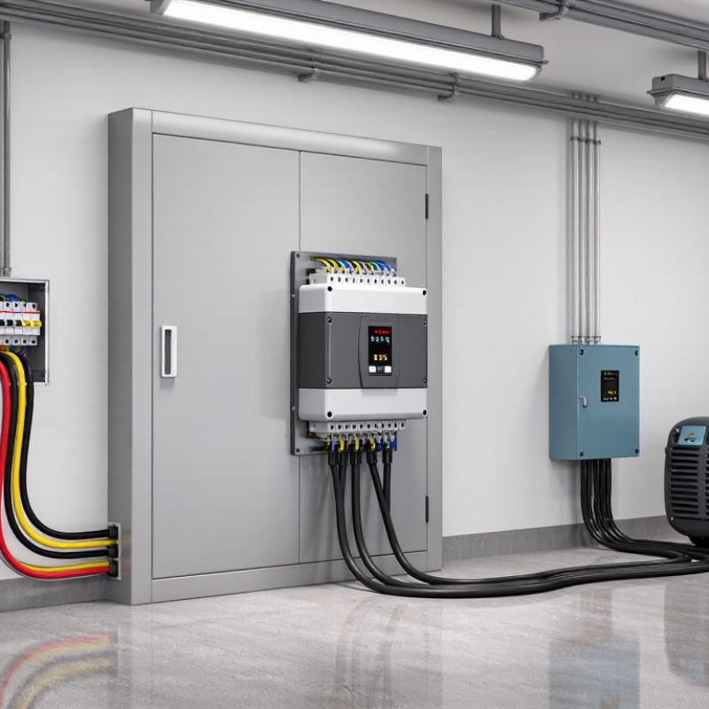
An automatic transfer switch (ATS) is electrical equipment that moves a load between two power sources. It monitors the normal supply and detects conditions such as a voltage loss or unacceptable voltage. When a backup source becomes available, the switch connects the load to it. When normal power returns, the ATS can transfer the load back. It does not generate electricity. A generator, battery system, or other source must provide the backup. In a facility, the switch may sit between the utility supply, a standby generator, and selected circuits such as emergency lighting or server equipment.
Timing matters. So does the load. An ATS must be selected for the system’s electrical ratings and the equipment it serves; installation and testing should follow applicable standards and qualified engineering guidance. Uptime Institute’s 2024 Annual Outage Analysis reported that 54% of surveyed organizations said their most recent significant outage cost more than $100,000. That figure covers varied outage causes, not ATS performance, but it shows why continuity planning deserves care. Automatic does not mean instantaneous. A generator may need time to start and stabilize, and a poorly matched switch can undermine the intended backup plan. The practical question is not only whether power transfers, but which circuits stay energized—and for how long.
What Is an Automatic Transfer Switch?
Main Components and Their Functions
An automatic transfer switch (ATS) connects a load to one of two power sources, commonly utility power and a standby generator. Its sensing circuit monitors voltage and frequency on the preferred source. Small voltage changes matter. If readings move outside configured limits, the controller recognizes a supply problem and starts the transfer sequence.
The controller is the decision-making unit. It checks whether the alternate source is stable, then signals the switching mechanism to move the load. That mechanism may use contactors or a motor-driven switch. Mechanical and electrical interlocks help prevent both sources from feeding the load at once. That pause is intentional. A generator may need time to reach steady output before the switch closes.
Power terminals carry current between the sources and the connected equipment. Their size and condition matter; loose connections can heat up under load. The enclosure protects internal parts from dust and accidental contact, while indicators can show which source is supplying power. Some systems include bypass-isolation hardware, allowing inspection or servicing without interrupting the load. A practical check includes examining connections and testing the transfer sequence under controlled conditions. Settings and inspection intervals vary by equipment and installation, so assumptions based on appearance alone can be misleading.
An automatic transfer switch (ATS) monitors two power sources and transfers a connected load from the normal source to an alternate source when needed.
Chart: Representative nominal voltages for common systems used with transfer equipment. Actual system ratings depend on the installation.
An automatic transfer switch (ATS) continuously monitors the normal supply, checking voltage and frequency against configured limits. A brief dip may not trigger a transfer; controllers often use adjustable time delays to avoid reacting to momentary disturbances. Not instantly. If the outage persists, the ATS signals a standby generator to start, then checks that its output is stable before moving the load. The generator provides power; the ATS manages the changeover.
NFPA 110 (2022 edition) defines a Type 10 emergency power supply system by its ability to restore power to designated loads within 10 seconds of a normal-supply failure. That is a system-level benchmark, not a promise that every ATS transfers in precisely 10 seconds. Real sites are messier. After utility power returns, the switch typically waits through a retransfer delay, then moves the load back and allows the generator to cool down. Open-transition switches briefly interrupt power during transfer; closed-transition designs can overlap sources momentarily when synchronization and applicable requirements permit. That detail matters. A poorly chosen delay or an untested generator can undermine an otherwise capable switch, so commissioning should include realistic load tests and recorded transfer times.
| Stage | What the ATS Does | What It Monitors or Controls | Important Detail |
|---|---|---|---|
| 1. Normal operation | Connects the load to the preferred power source, often the utility supply. | Source voltage and, where applicable, frequency and phase conditions. | The preferred source and acceptable operating limits are set for the installation. |
| 2. Power disturbance detected | Recognizes that the preferred source is outside configured limits or has failed. | Depending on the ATS, this can include undervoltage, overvoltage, frequency deviation, phase loss, or phase imbalance. | Detection thresholds and time delays vary by equipment and application; there is no single universal setting. |
| 3. Alternate source starts | If connected to a standby generator, sends a start signal after the configured response to a source failure. | Generator start and the alternate source’s electrical condition. | A generator typically needs time to start and reach acceptable voltage and frequency before the ATS transfers the load. |
| 4. Alternate source verified | Confirms that the alternate source is within the ATS’s configured limits. | Typically voltage and frequency; additional checks depend on the ATS design and system. | The ATS generally waits for acceptable conditions rather than transferring to an unstable source. |
| 5. Load transferred | Changes the load connection from the preferred source to the alternate source. | The switching mechanism and the selected transfer method. | Open-transition switching disconnects one source before connecting the other, causing a brief interruption. Closed-transition equipment can overlap sources momentarily when system conditions and design permit. |
| 6. Preferred source returns | Checks that the preferred source has returned and remains acceptable for the configured period. | Preferred-source voltage and other configured quality limits. | A return-to-source delay can help prevent repeated switching if the supply is unstable. |
| 7. Load re-transferred | Moves the load back to the preferred source using the configured transfer method. | Source availability and the ATS’s transfer sequence. | The generator may continue running without the load for a cooldown period before it stops. |
| Key purpose | Provides automatic switching between available power sources for connected loads. | Source condition, switching commands, and status indications. | An ATS switches sources; it does not generate electricity or, by itself, guarantee uninterrupted power. |
An automatic transfer switch (ATS) moves a load between normal and backup power when the preferred source fails. Common ATS designs include open-transition, closed-transition, delayed-transition, and bypass-isolation units. These labels describe different operating needs, not a simple ranking. IEC 60947-6-1 provides requirements for transfer switching equipment. The right choice depends on the load, the power system, and how much interruption equipment can tolerate.
With open transition, the switch disconnects one source before connecting the other. This break-before-make method is common and avoids paralleling sources, but lights may blink and sensitive equipment may reset. Closed transition briefly connects both sources during transfer, reducing interruption where the system permits parallel operation. Delayed transition pauses between sources, often allowing motor-driven loads to shed residual voltage. A bypass-isolation ATS lets technicians isolate the switching mechanism for maintenance while keeping the load supplied. A brief pause matters. In practice, a neat wiring diagram can hide complications: motor loads, residual voltage, and control settings all affect performance.
Selection should match the actual site. A data room, pump station, and small commercial panel do not have identical transfer requirements. Uptime Institute’s 2024 Annual Outage Analysis reported that 54% of surveyed respondents said their most recent significant outage cost more than $100,000; 16% reported costs above $1 million. The figures cover outages broadly, not ATS failures specifically, but they show why transfer behavior deserves careful review. Not always faster. Verify load compatibility, source coordination, and test procedures with qualified power-system professionals.
An automatic transfer switch (ATS) monitors the normal power supply and shifts a connected load to a backup source when voltage fails or falls outside set limits. In a small office, it may keep network equipment running; in a care facility, it can support essential circuits. When utility power returns, the ATS can transfer the load back, depending on its settings. That delay matters.
Common applications include commercial buildings, data rooms, healthcare facilities, and homes with standby generators. Selection starts with the load: check voltage, phase, current rating, and whether the switch must serve the whole building or selected circuits. Confirm that the ATS is compatible with the backup generator and its control signals. Consider the transfer method, enclosure rating, installation environment, and available maintenance access. A mismatched rating can cause nuisance trips or prevent the switch from handling the intended load. Installation and testing should be completed by qualified electrical professionals.
Tips: List the loads that must remain powered, such as a refrigerator, server rack, or pump. Check starting currents, not only running watts. Test under realistic conditions. A paper specification may look right, yet real loads can behave differently. Plan routine inspections and keep clear records of transfer tests.
1901 West Main Street
Washington, MO 63090
Main Directory: 1-800-227-4873
Email: sale@pangcofurniture.com

We’re always looking for talented individuals to join our team. Send us your resume using the form below. When a position comes available that matches your skillset, one of our team members will reach out to you.
"*" indicates required fields